

The electromagnetic shielding effectiveness of sealed modules cannot be determined by feel or appearance; it must be quantified through scientific, standardized verification and testing methods. After all, electromagnetic interference (EMI) is invisible and intangible, yet its destructive power is formidable. Especially in high-reliability sectors such as nuclear power, aerospace, high-end manufacturing, and offshore platforms, shielding performance must be clearly demonstrated and accurately measured.
The following are commonly used verification and testing methods in the industry, ensuring rigorous scrutiny from the laboratory to the field:
- Laboratory Testing: An Authoritative “Physical Examination Report”
This is the most accurate and authoritative testing method, typically conducted by third-party certified laboratories (such as SGS, TÜV, China Electric Power Research Institute, and TST SEAL Laboratories).
Shielding Effectiveness (SE) Testing
This is a core indicator measured in decibels (dB); higher values are better.
Test Principle: A sealed module (such as a shielded cabinet door or cable connector) is placed between two electromagnetically shielded chambers. Electromagnetic waves of a specific frequency (e.g., 1MHz-10GHz) are transmitted from one end, and the signal strength after penetration is received from the other end.
Calculation formula: SE = 10 × log₁₀(P₁/P₂), where P₁ is the incident power and P₂ is the transmitted power.
Qualification Criteria:
General Industrial Environments: >60dB (blocks 99.9999% of interference).
High-demand scenarios (such as medical and military applications): >80dB or even >100dB.
Conducted and Radiated Emissions Testing (EMC Compliance)
According to electromagnetic compatibility standards such as CISPR, FCC, and GB/T 18268, the entire device (such as a control cabinet) is tested for excessive electromagnetic noise emissions during operation. If the sealed module is well shielded, the overall radiation value will be significantly reduced.
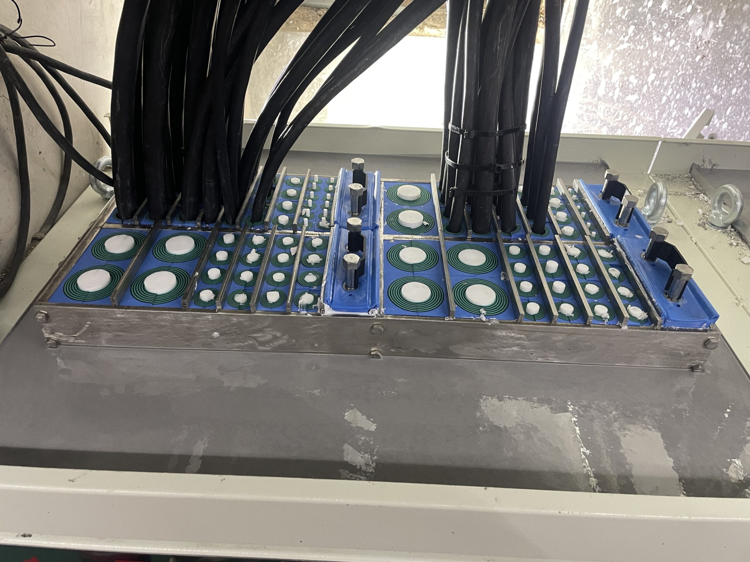
Shield Integrity (360° Termination) Inspection
Use a low-resistance tester to measure the contact resistance between the shield and the ground terminal. The ideal value should be <2.5mΩ. Excessive resistance indicates poor grounding, significantly compromising shielding effectiveness.
- On-site Inspection: “Health Monitoring” in the Real World
No matter how good the laboratory data is, it must stand up to field scrutiny. The following method is suitable for post-installation or O&M:
Spectrum Analyzer + Near-Field Probe Inspection
Operation: Place a near-field probe close to seals, cable entries, vents, and other locations, connected to a spectrum analyzer.
Diagnosis: If significant signal “leakage” is detected in critical frequency bands (such as the inverter operating frequency), it indicates a shielding vulnerability at that location.
Application: Identify shielding weaknesses in cabinets and control boxes.
Electromagnetic Leakage Scanning System
Some high-end equipment (such as EMSCAN) can perform “electromagnetic thermal imaging” of the entire cabinet, visually displaying electromagnetic leakage “hotspots” and helping to quickly locate sealing defects.
Signal Quality Monitoring
Method: Use a network analyzer or oscilloscope to observe the signal waveform on a communication link using shielded cable (such as industrial Ethernet or RS485).
Diagnosis: Severe signal distortion, noise superposition, and increased bit error rates may indicate shield failure or poor grounding.
III. Structural and Workmanship Inspection: Preventive “Physical Inspection”
Many shield failures are caused by improper installation, so visual and workmanship inspections are equally important:
360° Metal-to-Metal Contact Inspection:
Sealing surfaces (such as cabinet doors) must have a conductive backing (such as conductive rubber or wire mesh) and maintain continuous, uninterrupted metal-to-metal contact with the cabinet metal frame. There must be no paint, oxide layers, or gaps.
Cable Shield Termination Quality:
The shield should be crimped 360 degrees. Do not use a “pigtail” connection (twisting a single wire), as this will negate the high-frequency shielding effectiveness.
Use shield clamps or EMI connectors to ensure a secure connection to the cabinet metal housing.
Grounding System Integrity:
Check whether the grounding wire is secure and whether the grounding resistance meets the requirements (usually <1Ω). Even the best shielding effectiveness is negligible if the grounding is inadequate.
- Industry Trend: From “Post-Test” to “Real-Time Warning”
In the future, electromagnetic shielding testing is moving towards intelligence:
Embedded Sensors: Electric/magnetic field sensors are built into key sealing joints to upload shielding status data in real time.
Digital Twin + AI Analysis: Shielding performance data is incorporated into the equipment digital twin model, and AI predicts potential risks, enabling “predictive maintenance.”
Shielding effectiveness must be “measurable, manageable, and traceable.”
Verifying the electromagnetic shielding effectiveness of a sealing module is not a one-time “pass” test; it requires a full lifecycle management system encompassing design, manufacturing, installation, and operation and maintenance. From precise laboratory measurements to dynamic on-site monitoring and rigorous process control, every step is crucial.
Remember: “Shielding” is not simply a matter of attaching a metal sheet; it is a systematic project encompassing “materials + structure + grounding + process.” Only through scientific verification can we ensure that this “invisible line of defense” is truly reliable and can protect the “quietness” and “awakeness” of the equipment in electromagnetic storms.