
It’s 2026! Friends, would you like to know about the new changes in wire gauges? TST SEAL Nico has analyzed and compiled an authoritative 2026 AWG/MCM wire gauge metric conversion table based on IEEE, NEC (National Electrical Code), and ASTM B258 standards from massive amounts of data. Those who need it can refer to it themselves. If you have any questions, please feel free to contact me via email (Email: alixich@tstcables.com).
Although the physical dimensions of AWG (American Wire Gauge) remain constant, in international trade and engineering applications in 2026, the accuracy requirements for the “actual cross-sectional area” and “nominal metric equivalent value” are becoming increasingly stringent, especially in the conversion between UL certification (American standard) and IEC standards (European/Chinese standard).
Below is a detailed data table and engineering analysis compiled by TST seal.
- AWG Metric Conversion Table (Power and Control Cables)
This table covers the most commonly used range of cables, from signal control to power cables.
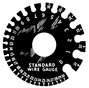
Key Formula: Diameter dn = 0.005 inch × 92(36−n)/39
Note: “Metric corresponding nominal values” are not mathematically absolute equalities, but rather the nearest standard metric size typically used in engineering.
AWG wire gauge | Conductor diameter (mm)
(Single solid conductor) | Conductor cross-sectional area (mm²)
(Precise physical value) | Metric equivalent nominal value (mm²)
(Engineering substitution suggestion) | Typical application scenarios |
30 AWG | 0.254 | 0.0503 | 0.05 | Electronic wires, ultra-fine sensors |
28 AWG | 0.320 | 0.0804 | 0.08 / 0.1 | Data transmission, ribbon cables |
26 AWG | 0.404 | 0.128 | 0.14 | Signal control, network cables |
24 AWG | 0.511 | 0.205 | 0.2 / 0.25 | Sensors, low-voltage signals |
22 AWG | 0.643 | 0.324 | 0.34 / 0.5 | Dashboard internal wiring |
20 AWG | 0.813 | 0.519 | 0.5 | Automotive circuits, low-power power supplies |
18 AWG | 1.024 | 0.823 | 0.75 | Lighting fixtures, home appliance power cords |
16 AWG | 1.290 | 1.31 | 1.5 | Equipment main power supplies, control cabinets |
14 AWG | 1.628 | 2.08 | 2.5 | Building wiring (15A/20A) |
12 AWG | 2.052 | 3.31 | 4.0 | Socket main circuit (20A/25A) |
10 AWG | 2.588 | 5.26 | 6.0 | High-power equipment, photovoltaic lines |
8 AWG | 3.264 | 8.37 | 10 | Incoming power lines, motors |
6 AWG | 4.115 | 13.30 | 16 | Industrial power distribution |
4 AWG | 5.189 | 21.15 | 25 | Main lines |
2 AWG | 6.543 | 33.62 | 35 | Battery connections, UPS |
1 AWG | 7.348 | 42.41 | 50 | – |
1/0 AWG | 8.252 | 53.49 | 50 / 55 | (i.e., 0 AWG) |
2/0 AWG | 9.266 | 67.43 | 70 | (i.e., 00 AWG) |
3/0 AWG | 10.40 | 85.01 | 95 | (i.e., 000 AWG) |
4/0 AWG | 11.68 | 107.2 | 120 | (i.e., 0000 AWG) Maximum AWG |
- MCM/kcmil Metric Conversion Table for Large Gauges
When the wire gauge exceeds 4/0 AWG, the American standard uses kcmil (thousand circular mils) or formerly known as MCM for measurement.
Conversion factor: 1 kcmil ≈ 0.5067 mm²
This data is crucial for heavy-duty industrial cables (such as those used in cable sealing module applications).
US Standard Size (kcmil/MCM) | Cross-sectional area (mm²)
(Exact value) | Corresponding metric cable (mm²)
(IEC 60228 standard) | Notes: |
250 MCM | 126.7 | 120 / 150 | Between the two, 150 is often chosen to ensure current carrying capacity.
|
300 MCM | 152.0 | 150 | Almost perfectly matched. |
350 MCM | 177.3 | 185 | Very close. |
400 MCM | 202.7 | 185 / 240 | 240 is often used as a substitute. |
500 MCM | 253.4 | 240 / 300 | 240 is slightly smaller, 300 has more margin. |
600 MCM | 304.0 | 300 | High matching degree. |
750 MCM | 380.0 | 400 | – |
1000 MCM | 506.7 | 500 | Almost perfectly correspondence |
III. Technical Analysis by TST SEAL Senior Engineer
- The Pitfalls of “Solid” vs. “Stranded” The diameters in the table above typically refer to a single solid conductor. As a factory engineer, you must be aware of the following when designing cables or sealing modules:
Stranded Outer Diameter Expansion: The vast majority of industrial cables are multi-stranded. Due to gaps in the stranding, the actual conductor outer diameter is 10%~15% larger than the calculated solid value.
Engineering Examples:
10 AWG Solid Diameter ≈ 2.59 mm
10 AWG Stranded (7 strands) Diameter ≈ 2.95 mm
Impact: If your sealing module is designed for solid diameter, encountering stranded wires can lead to seal failure or installation difficulties.
- Risks of “Gap Jumping” Between Metric and US Units
When manufacturing non-standard products for overseas markets, the area most prone to problems is the region where AWG and mm² are not perfectly equivalent.
Risk Point: 14 AWG (2.08 mm²) is often mistaken for 2.5 mm². In reality, 2.5 mm² has a higher current carrying capacity and cost than 14 AWG. If the customer requires UL-certified 14 AWG, directly using 2.5 mm² in your design may lead to cost overruns; conversely, replacing 2.5 mm² with 14 AWG may result in substandard resistance (IEC standard).
- Special Characteristics of High-Temperature Cables
For high-temperature cables (such as fluoroplastic and silicone rubber insulation), although the conductor follows the above AWG standard, the insulation thickness is usually thinner or varies significantly compared to ordinary PVC cables.
Recommendation: When designing wall penetration seals or joints, do not rely solely on the AWG conversion table. Always request the cable’s Spec Sheet from a TST seal cable engineer to confirm the OD (Outer Diameter), as different withstand voltages require different OD values. The insulation thickness varies significantly depending on the industry, equipment, environment, and voltage rating (300V vs 600V).
Your requirement of “current carrying capacity first, resistivity second” aligns perfectly with the practical logic of cable design: ensure no overheating first (safety), then ensure voltage drop and loss meet standards (performance).
The following is an in-depth comparative analysis based on NEC 2023/2026 (US standard) and IEC 60364-5-52 (European/Chinese standard).
Part 1: Ampacity Calculation Analysis As a high-temperature cable manufacturer, your biggest pain point is often: “My cable is 200°C resistant, why can customers only use it at 75°C or 90°C?” The core issue lies in the differences in standard systems and the “weakest link” effect.
- NEC vs IEC: Practical Comparison of Commonly Used Specifications’ Ampacity
Baseline Conditions:
NEC (US Standard): Based on Table 310.16, ambient temperature 30°C, 3 conductors in a conduit (Raceway). IEC (European Standard): Based on IEC 60364-5-52, ambient temperature 30°C, installation method B2 (conduit/trough).
Insulation Class: Compared to common 90°C grade materials (e.g., XHHW-2, THHN vs XLPE).
AWG (American Standard) | Corresponding metric units (mm²) | NEC Current Carrying Capacity (90°C Insulation) (Table 310.16) | IEC Current Carrying Capacity (90°C Insulation) (Table B.52.5) | Engineer’s Interpretation (Difference Analysis) |
14 AWG | 2.5 mm² | 25 A | 30 A | IEC 2.5mm² has a slightly larger physical cross-section (2.08 vs 2.5), and the IEC heat dissipation model is slightly more lenient. |
12 AWG | 4.0 mm² | 30 A | 40 A | A major difference: NEC has strict limitations on 12 AWG, often restricted by circuit breaker (20A) limits. |
10 AWG | 6.0 mm² | 40 A | 52 A | 6.0mm² is a very strong specification in European standards, with a significantly higher current carrying capacity than 10 AWG. |
8 AWG | 10 mm² | 55 A | 71 A | Selection pitfall: If the customer designs according to the European standard 70A, selecting 8 AWG will cause overheating! 6 AWG must be used. |
6 AWG | 16 mm² | 75 A | 96 A | Similarly, for high current applications, AWG specifications often need to be “one size larger” to align with the metric system. |
⚠️ 2026 Trend Alert (NEC Update):
The term OCPD (Overcurrent Protective Device) will be more standardized in NEC 2026 and its related drafts.
Key Limitation: While 14 AWG 90°C insulation can withstand 25A, NEC 240.4(D), a “small conductor rule,” typically imposes a 15A limit on its protective device. When dealing with overseas markets, do not rely solely on the “maximum theoretical current” in cable specifications; you must inform customers that it is “limited by circuit breaker rules.” This demonstrates professionalism.
- The Weakest Link in High-Temperature Cables
Misconception: Customers who purchase FEP/PTFE (200°C) cables assume they can carry current at 200°C.
Reality (NEC 110.14(C)): The rated temperature of a circuit depends on the “least heat-resistant component.”
Terminals: Most circuit breakers and contactors have terminal temperatures rated at only 75°C.
Conclusion: Even if your cable can withstand 200°C, when connecting to a standard distribution cabinet, you must refer to the 75°C table for current carrying capacity.
So, what is the value of high-temperature cables?
Value Point 1 (Derating Buffer): When ambient temperatures reach 60°C or 80°C (e.g., in steel mills or chemical plants), the current carrying capacity of a standard 90°C cable needs to be reduced, while a 200°C cable can still maintain 100% current carrying capacity.
Value Point 2 (Safety): The high-temperature insulation layer will not melt during short circuits or overloads.
Part Two: Resistivity & Plating Analysis Having addressed current carrying capacity (heat generation), let’s look at resistivity (voltage drop). This is crucial for conductor selection in TST Seal’s non-standard cable sealing modules, especially when nickel or silver plating is involved.
- Basic Physical Data (20°C Baseline)
Conductor Materials | Conductivity (% IACS) | resistivity (Ω·mm²/m) | ASTM Standard | Typical Applications: |
Annealed Soft Copper (Bare Copper) | 100% | 0.017241 | ASTM B3 | Standard power cable |
Tinned Copper | ~96-99% | Slightly higher than copper | ASTM B33 | Oxidation resistant, easy to weld (150°C) |
Silver Plated Copper | >100% | < 0.01724 | ASTM B298 | High-frequency signal, ultra-high temperature resistant (200°C) |
Nickel Plated Copper | 90-96% | 0.0178 – 0.019 | ASTM B355 | Extreme high temperature (260°C+), corrosion resistant |
- The “Resistance Trap” of Nickel-Plated Copper
Many high-end customers specify ASTM B355 nickel-plated copper for extreme environments, but you must account for the resulting increase in resistance.
Principle: Nickel’s conductivity is only about 25% of copper’s. The thicker the plating, the more significant the decrease in overall conductivity.
ASTM B355 Grade Impact:
Class 2 (2% nickel content): Minimal impact on resistance, almost equivalent to bare copper.
Class 10 (10% nickel content): Resistivity begins to increase significantly.
Class 27 (27% nickel content): Used in 400°C+ environments, DC resistance may be 5-10% higher than standard copper wire.
Engineering Impact: If the customer’s wiring is very long (such as submarine cables or large factory wiring), this 5% increase in resistance may lead to excessive voltage drop, and you may need to recommend upsizing the wire gauge.
- The “Skin Effect” Advantage of Silver-Plated Copper
If your cables are used for high-frequency data transmission or high-power pulses:
Current tends to flow on the surface of the conductor (skin effect).
Because silver has higher conductivity than copper, the silver plating can actually reduce high-frequency resistance. This is an advantage that nickel-plated wire cannot match.